Archives
All posts for the month November, 2013

At MOMA, date 1911

iPhone photo

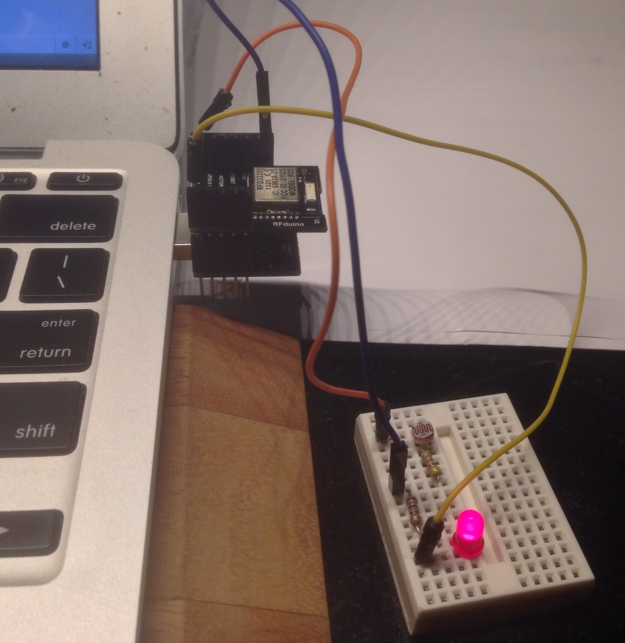
Here is an Rfduino mounted on a small breadboard with three circuits — with TMP36 temperature sensor, CdS photo resister, and LED (not visible). At the moment the Arduino sketch is wired to send temperature data, and the LED is turned off. The TMP36 circuit, from TMP36 to RFduino is: GND (left) to GND, middle pin to GPIO 1, right pin to AREF. Left is left when you face the flat side of the TMP36, opposite to what is shown in the picture.
I am impressed by the communication performance and reliability of RFduino. In my office about ten feet from the device, the bluetooth signal strength is about -57db. Forty feet around the corner and down the hall, the reading is -85 db but sometimes shows -125 db. But I can reliably connect and read the sensor. Twice as far away around another corner the connection is iffy — connection about half the time.
Another feature I like is that all the GPIO pins can be used for analogue read. You do not have to do anything special. Just make the declaration int sensor = 1; and then say float sensorReading = analogRead(sensor); in your loop to read sensor data from GPIO pin 1.
References:
RFduino @ github — source code for RFDuino’s temperature code (measures CPU temperature) and iPhone app code. My code based on this.
rfduinoSensor — at github
Purpose: read data from any analogue sensor using RFDuino, display that data on iPhone. Communicaton is by bluetooth.
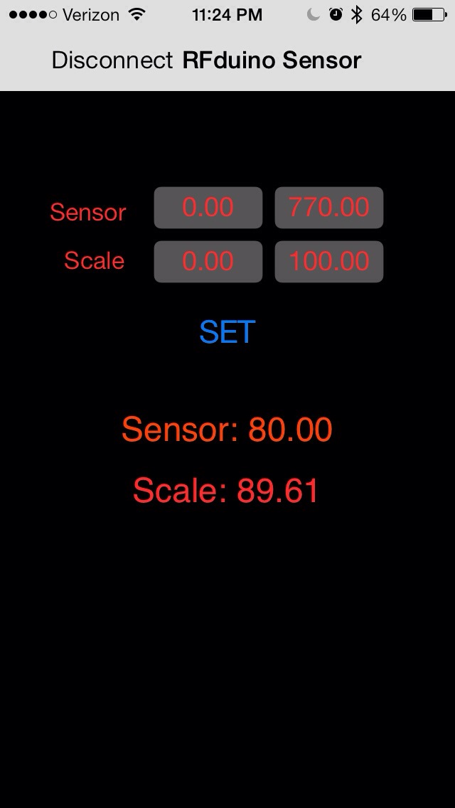
The iPhone app allows the user to set the minimum and maximum sensor values and the minimum and maximum scale values. For example, suppose that the minimum and maximum sensor value are set to 0 and 760, and the minimum and maximum scale values are set to 0 and 100, the a sensor reading of 380 will be displayed as a scale reading of 50. (See note on scale calibration below).
The rightmost blue button, with text “Normal” or “Reversed” is used to toggle the scale direction. For example, in normal mode, 760 gives a scale reading of 100, while in reversed mode, it gives a scale reading of 0.
This project consists of three parts:
1. The rfduino board (see http://www.rfduino.com) connected to an analogue sensor circut and to a power supply — five volts is best, but 3v works and so should 1.5v, although I have not tested that.
The basic circuit: GPIO pin 1 to sensor to resistor to GND. Optional: GPIO pin 2 to LED to resistor to GND — blinks to show that circuit is operational. Note that when using a light sensor at low light levels, the blinking LED affects the light readings.
2. A arduino sketch (Folder = Sensor_RFDuino) that you upload to the RFDuino.
3. An iPhone app that displays the sensor data. Communication with the rfduino is by Bluetooth.
Scale calibration. I used a cadmium sulfide photoresistor for this project with a 9.7 KOhm resistor. The circuit was GPIO pin 1 on RFDuino to photoresistor to resistor to GND. To calibrate, I first removed the photoresistor. This gave me the maximum sensor reading of 748. Then I attached a jumper to the pins where the photoresistor normally goes to short this part of the circuit. This gave me a minimum sensor reading of 66. I entered these values into the two “Sensor” fields on the app and pressed “Set”. Next, I set the scale mode to “Reversed”. This was so that bright light would read high on the scale, low light low.
NOTES: (1) at the moment, you need to put the folders containing the iphone code in the folder RFDuino/iPhone\ Apps so that it will see the rfduino library — RFDuino.h, etc. I will remedy this at a later date. For now, see https://github.com/RFduino/RFduino for the code needed.
(2) The code for this project is derived from Arduino sketch and iPhone code for the rfduinoTemperature project at https://github.com/RFduino/RFduino.