Last night I assembled the Quick2Wire interface board for the Raspberry Pi. Assembly was straightforward. To test the board, I downloaded gpi-admin using the instruction on MIRA/DEV’s blog. This blog has some very good information: hardware set-up for a circuit with one LED and one switch to test the RPi, installation of software, testing, etc. All good until I tried the commands
   sudo echo out > /sys/devices/virtual/gpio/gpio7/direction
   sudo echo 1 > /sys/devices/virtual/gpio/gpio7/value
   sudo echo 0 > /sys/devices/virtual/gpio/gpio7/value
At this point, I got “permission denied” errors — Hmmm. I also tried my previously tested program blink.py which used the RPi.GPIO library and GPIO.setmode(GPIO.BCM). The goal was to blink the green LED on the Quick2Wire board. Result, with various choices of output pin numbers: nada.
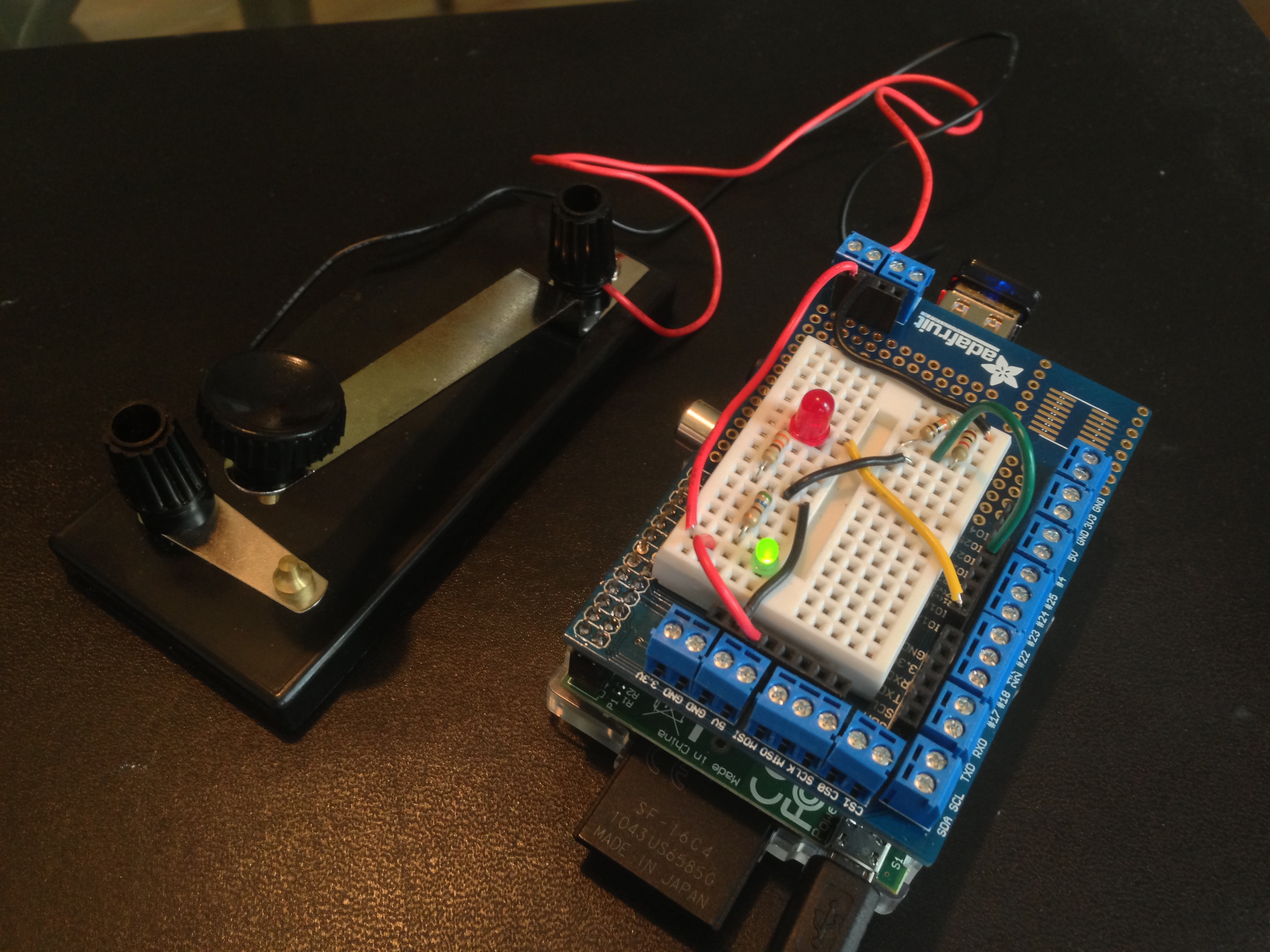
I wasn’t sure that the board was working, since this is the second one I’ve made. To troubleshoot, I first rigged up the little test circuit you see in the photo below and in the schematic above. It is an LED with a current-limiting resistor and a polarity-protecting diode, the free ends attached to two female headers. (continued below)

TESTS
(1) On the Quick2Wire boards there is a 3-pin male header with pins for 5V, 3.3V, GND. I attached the test circuit to 5V and GND — it glowed as it should. Same for 3.3V and GND. So I decided that the board was probably working.
(2) I left the black lead of the tester attached to GND, inserted a length of wire bared at each end into the other lead, and then into GPIO pin on the board labeled p0 on the board. This pin is one of a set of ten, labeled GND, p0, p1, …, p7, 3v3. Result with blink.py again: nada.
(3) I realized that I was confused about the various systems of pin numbering — GPIO, BOARD, Wiring Pi. So I modified blinktest.py to give the option of using any of the three systems:
   $ sudo python blinktest.py -g 18    # Blink LED on GPIO pin 18
   $ sudo python blinktest.py -w 1     # Blink LED on Wiring Pi pin 1
   $ sudo python blinktest.py -b 12    # Blink LED on RPi board pin 12
The code for blinktest.py is at github.
With the blinktest.py and the test circuit in hand, I discovered that (a) the Quick2Wire board uses GPIO numbering on the Python side but Wiring Pi on the labels of the GPIO pins; (b) The jumper LED_ENABLE determines whether Wiring Pi pin 1 or LED is active. (c) I could not get Wiring Pi pin 2 to blink the test circuit. I’ll try swapping out the RPi later to see if it is at fault.
Charts and info on GPIO pins: Raspberry Pi Spy
 Of late I’ve been doing some experiments with generative art using Elm, the functional language by Evan Czaplicki. Above is one example. It is created by repeatedly subdividing a square into quadrilaterals, modifying the colors as one goes. A key factor is finding a proper balance between order and randomness. For more details, see these notes. The code is on GitHub.