
Camera: iPhone5
zipTimer: an iPod/iPhone app for pacing piano practice, cooking, workouts, you name it.
Camera: iPhone5
zipTimer: an iPod/iPhone app for pacing piano practice, cooking, workouts, you name it.


Camera: iPhone5

This is a short report on how to connect Quick2Wire’s analogue board directly to a Raspberry Pi. The key is the pinout for for the six-pin boxed headers on the Q2W board. I ignored the 5V and Int lines, running lines only for 3.3V, GND, SCL, and SDA. I ran these to the corresponding pins on the Pi, then executed sudo python3 pcf8591read.py as before. Result? Success! I could read the potentiometer connected as in my previous post on the Q2W analogue board. See that code for comments on the Python code used to read the potentiometer.

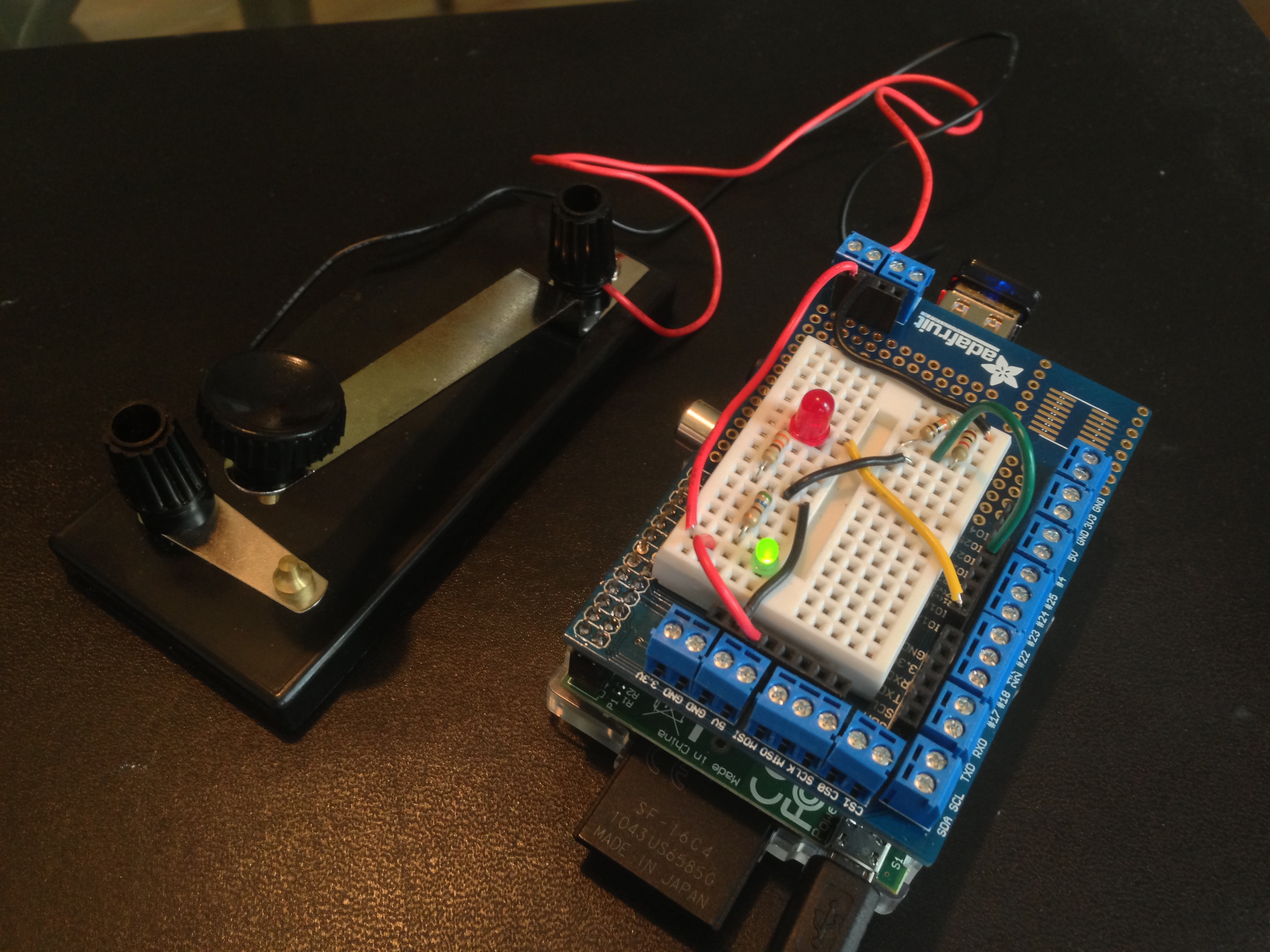
Below is an improved set-up for connecting the Quick2Wire analogue board to the Raspberry Pi. I mounted the Q2W board on one end of a full-size breadboard with double-sided tape and inserted a Pi Cobbler on the other end. The analogue headers of the Q2W board face the inside of the breadboard.
I didn’t have the right kind of jumpers to connect the Q2W board to the breadboard, so I cut one end off of each of four female-to-female jumpers, soldered on a length of wire, and sealed the exposed connection with heat-shrink tubing. We don’t want any short circuits! With the female-to-male jumpers in had, it ws easy to set up the circuit.
Edit: On the first try, the RPi could not read data from the Q2W board. I then remembered that the left and right halves of the board are electrically separate, so I installed the red and blue jumpers you see in the center, bottom of the photo below. I also added the little LED circuit you see in the lower left, so that there is an LED to indicate whether the full board is receiving power.


Work by 31416kungfu, age 10-11
Last night I assembled the Quick2Wire analogue board. The software setup took a little bit of fiddling, after which I was able to make the simple tests described at Quick2Wire and a measurement with a potentiometer. The source I found most useful was the post at www.miraculum.ch.
1. Set up ictools as described at adafruit.
2. Install the quick2wire-python-api in a directory /home/git as Miraculum recommends. (Make this directory if need be).
   $ cd git
   $ git clone https://github.com/quick2wire/quick2wire-python-api.git
3. Find the file pcf8591read:
$ find /home /usr -name pcf8591read
Make a copy of this file in ~/git and rename it as pcf8591read.py. Then add the line indicated below to the code so that the head of the file looks like this:
   #! /usr/bin/env python3

   import sys
   sys.path.append(r'/home/pi/git/quick2wire-python-api/')  # add this
   from quick2wire.i2c import I2CMaster
   from quick2wire.parts.pcf8591 import *
As noted in Miraculum’s post, the added line ensures that the program finds the needed parts of the quick2wire-python-api.
4. On the Quick2Wire Analogue board, run a jumper from AIN0 to GND. Then say sudo python3 pcf8591read.py. You should see this:
pi@raspberrypi ~/git $ sudo python3 pcf8591read.py
read: 1 : 0.0
read: 2 : 0.0
read: 3 : 0.0
5. Now run the jumper from AIN0 to VREF. You should see this:
pi@raspberrypi ~/git $ sudo python3 pcf8591read.py
read: 1 : 1.0
read: 2 : 1.0
read: 3 : 1.0
6. Attach a potentiometer as follows: one outside lead to GND, the other to VREF, the middle lead to AIN0. Then test. You will get something like this as you rotate the potentiometer:
pi@raspberrypi ~/git $ sudo python3 pcf8591read.py
read: 1 : 0.0
read: 2 : 0.0
read: 3 : 0.0
read: 4 : 0.06274509803921569
read: 5 : 0.14901960784313725
read: 6 : 0.20392156862745098
read: 7 : 0.2627450980392157
read: 8 : 0.3254901960784314
read: 9 : 0.39215686274509803
read: 10 : 0.47058823529411764
read: 11 : 0.5686274509803921
read: 12 : 0.6705882352941176
read: 13 : 0.796078431372549
read: 14 : 0.9686274509803922
read: 15 : 1.0
read: 16 : 1.0

RPi with Quick2Wire interface and analogue boads
Last night I assembled the Quick2Wire interface board for the Raspberry Pi. Assembly was straightforward. To test the board, I downloaded gpi-admin using the instruction on MIRA/DEV’s blog. This blog has some very good information: hardware set-up for a circuit with one LED and one switch to test the RPi, installation of software, testing, etc. All good until I tried the commands
   sudo echo out > /sys/devices/virtual/gpio/gpio7/direction
   sudo echo 1 > /sys/devices/virtual/gpio/gpio7/value
   sudo echo 0 > /sys/devices/virtual/gpio/gpio7/value
At this point, I got “permission denied” errors — Hmmm. I also tried my previously tested program blink.py which used the RPi.GPIO library and GPIO.setmode(GPIO.BCM). The goal was to blink the green LED on the Quick2Wire board. Result, with various choices of output pin numbers: nada.
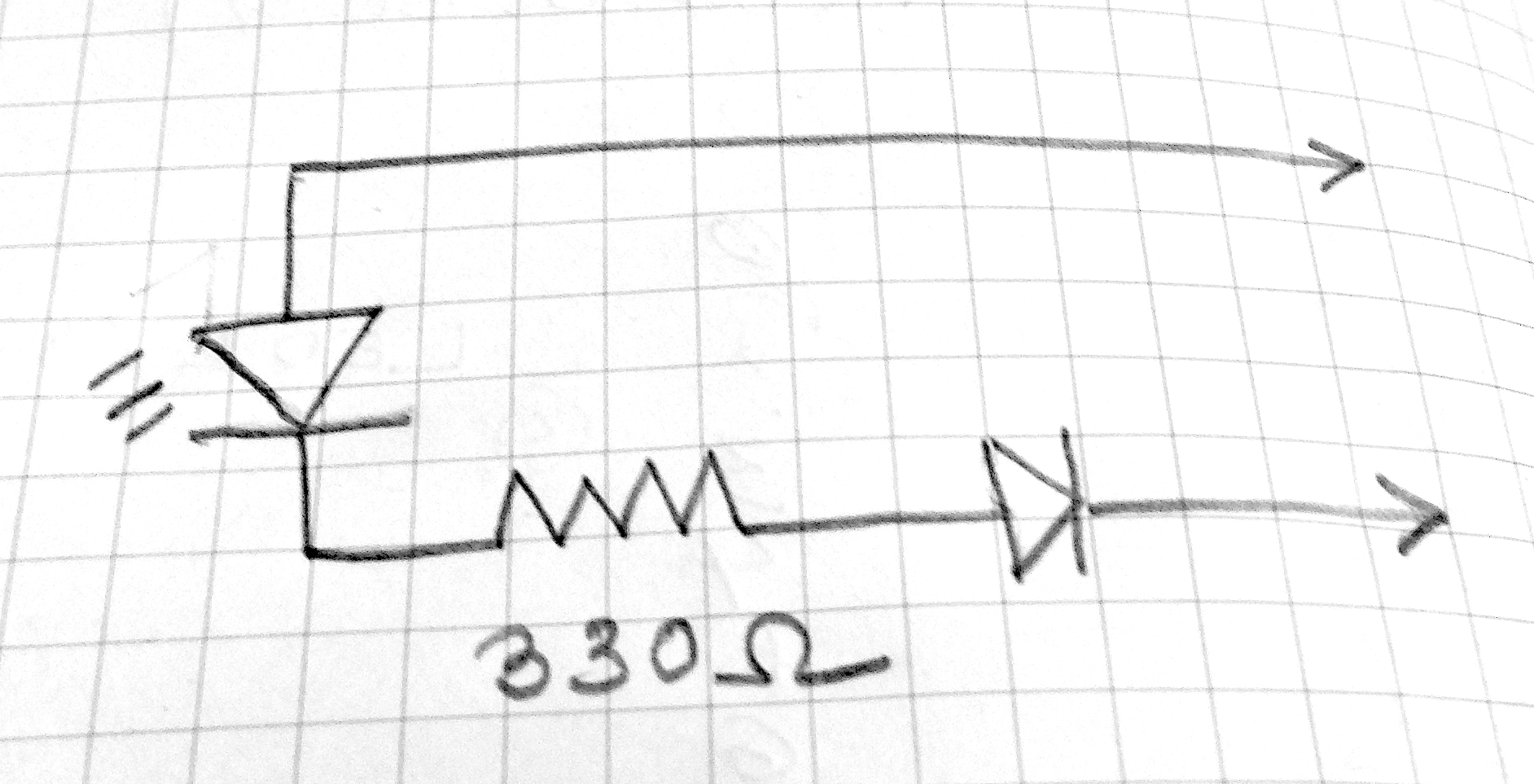
I wasn’t sure that the board was working, since this is the second one I’ve made. To troubleshoot, I first rigged up the little test circuit you see in the photo below and in the schematic above. It is an LED with a current-limiting resistor and a polarity-protecting diode, the free ends attached to two female headers. (continued below)

TESTS
(1) On the Quick2Wire boards there is a 3-pin male header with pins for 5V, 3.3V, GND. I attached the test circuit to 5V and GND — it glowed as it should. Same for 3.3V and GND. So I decided that the board was probably working.
(2) I left the black lead of the tester attached to GND, inserted a length of wire bared at each end into the other lead, and then into GPIO pin on the board labeled p0 on the board. This pin is one of a set of ten, labeled GND, p0, p1, …, p7, 3v3. Result with blink.py again: nada.
(3) I realized that I was confused about the various systems of pin numbering — GPIO, BOARD, Wiring Pi. So I modified blinktest.py to give the option of using any of the three systems:
   $ sudo python blinktest.py -g 18    # Blink LED on GPIO pin 18
   $ sudo python blinktest.py -w 1     # Blink LED on Wiring Pi pin 1
   $ sudo python blinktest.py -b 12    # Blink LED on RPi board pin 12
The code for blinktest.py is at github.
With the blinktest.py and the test circuit in hand, I discovered that (a) the Quick2Wire board uses GPIO numbering on the Python side but Wiring Pi on the labels of the GPIO pins; (b) The jumper LED_ENABLE determines whether Wiring Pi pin 1 or LED is active. (c) I could not get Wiring Pi pin 2 to blink the test circuit. I’ll try swapping out the RPi later to see if it is at fault.
Charts and info on GPIO pins: Raspberry Pi Spy
mio.py is “my” io library for Raspberry Pi. At present it is a kind of “hello world” program that demonstrates how work with one digital input, e.g., a switch, and one digital output, e.g., an LED. Below are (a) a photo of the Raspberry rigged up with a circuit managed by miO, (b) a description of the package, (c) some output on the command line, (d) a circuit diagram.
The (Python) code is at github.
(a) MIO RUNNING ON PI
(b) MIO: COMMAND SUMMARY
Suppose that LED is pin 17 and SWITCH is pin 23:
blink(LED, 0.1, 0.3) — blink LED, on for 0.1 second, off for 0.3 secondsread(SWTICH) — read SWITCH: print 1 ON the first time it is closed, then the time it was held closed when it opens, then print 2 ON when it is closed the second time, etc.control(LED, SWITCH) — control LED with SWITCH. This function is like read, except that the LED blinks when the switch is closed.These functions can be invoked fromt the command line: (a) sudo python mio.py blink, (b) sudo python mio.py read, (c) sudo python mio.py control.
(c) SOME OUTPUT
pi@raspberrypi ~/gpio $ sudo python3 mio.py read
    1 ON
      1.09
    2 ON
      1.75
    3 ON
      0.13
    4 ON
      0.11
(d) CIRCUIT DIAGRAM
Let the switch have terminals A and B.

   A --- 3.3V

              |--- 1K resistor --- Pin 23
   B --- T ---|
              |--- 10K resistor ---GND

   Pin 17 --- LED --- 330 Ohm resistor --- GND

Chang W. Lee/New York Times
And How Many Rains Must Fall Before the Stains Are Washed Clean?
This line in the famous poem by the Urdu poet Faiz Ahmed Faiz (1911-1984) is a verbal counterpart to the installation at the Metropolitan Museum of Art by Pakistani artist Imran Qureshi. See the New York Times article, May 16, 2013 by Ken Johnson.
Qureshi writes: “These forms stem from the effects of violence. They are mingled with the color of blood, but, at the same time, this is where a dialogue with life, with new beginnings and fresh hope starts.”
The exhibit runs from May 14 through November 3, 2013. Mr. Qureshi, who a created similar installation for the 2011 Shariah Biennial in the United Arab Emirates, is also know for his paintings in the style of 16-th and 17-th century Indian miniatures.
CLIPPINGS
(1) On war, from december71.wordpress.com
Perhaps, faiz has summed it up better than any other:
kab nazar meiN aaye gi be daaGh sabze ki bahaar
khoon ke dhabe dhuleiN ge kitni barsaatoN ke baad
When will we again see a spring of unstained green?
After how many monsoons will the blood be washed
from the branches?
Faiz Ahmed Faiz: On return from Dhaka: Hum Ke Thehray Ajnabi
(2) SIX URDU POEMS
Film: Meherjaan: A Story of War and Love
(3) Gunshots on Warm Spring Evenings
(4) In the world of print, it falls within the bounds of copyright law to quote small bits of text. Above, I have made a visual quote of Chang W. Lee’s powerful photograph. I hope that this will be viewed both as acceptable practice and become common one, helping to disseminate good images more widely in the same way that good text is disseminated.

